
At a glance
- Category
- An experimental research report from the Langley 8-foot transonic tunnel that proposes a physical concept and tests it. Four wing-body models are compared, through schlieren photographs, wall Mach numbers and balance drag, with specially made bodies of revolution. Three further models apply the concept as a design method.
- Context
- Near the speed of sound, wings and bodies interfered with each other's drag in ways that were large, variable and, in the author's words, not understood even qualitatively (p. 1). Transonic similarity rules and linear theory had been applied only in limited analyses. The work builds on Whitcomb and Kelly's flow study of a 45° swept wing-fuselage (NACA RM L52D01), on body-of-revolution drag data (RM L8A28b, RM L9J27), and on Busemann's observation that stream-tube areas barely change with velocity near Mach 1 (NACA TN 2687).
- Contributions
- The concept, stated and tested: near the speed of sound the zero-lift drag rise of a thin, low-aspect-ratio wing-body combination is primarily dependent on the axial development of the cross-sectional areas normal to the airstream (p. 21).
- Side-by-side schlieren and wall-Mach-number surveys at Mach 0.85 to 1.10 showing nearly identical shock patterns for a wing-body combination and its comparable body of revolution.
- Drag-rise measurements for unswept, delta and swept wings on a cylindrical body, and the swept wing on a curved body, each against its comparable body.
- A physical explanation in terms of nearly invariant stream tubes and disturbances concentrated in planes normal to the stream.
- A design rule: indent the body so the combination's area distribution matches the original body's. This cut the wing's drag-rise increment by about 60 percent for the unswept and delta wings and removed it for the swept wing up to Mach 1.04.
Summaryp. 1
Shock patterns and drag-rise increments for representative wing–central-body combinations are compared with those for bodies of revolution that have the same axial distribution of cross-sectional area normal to the airstream. From these comparisons the report concludes that near the speed of sound the zero-lift drag rise of a low-aspect-ratio thin-wing–body combination depends mainly on that area distribution. Any two such configurations with the same distribution should then have about the same drag rise (p. 1).
Such indentations greatly reduced or eliminated the zero-lift drag-rise increments associated with the wings near the speed of sound.Summary, p. 1
The second half of the summary is the practical payoff. Bodies were indented so that wing plus body had the same area distribution as the original body alone, and that change largely removed the drag rise the wings had added.
Introductionp. 1
Designers had no general means of explaining, even for a wing alone, how transonic drag rise varied with plan form and section. Nor was there even a qualitative understanding of the large, variable zero-lift drag interference between practical wings and bodies near Mach 1 (p. 1).
Two observations pointed the way. For a swept wing on a central body, the zero-lift drag rise was due mainly to shock losses (RM L52D01), and the shocks around that complex shape at zero lift looked like those expected for a body of revolution with the same lengthwise development of cross-sectional area. The combination's drag rise was also about the same as that of a body of revolution with roughly the same area development. Together with a preliminary consideration of the general physical nature of the flow, this led to the concept under test (p. 1).
To test it, the flow fields and drag rise of four wing–central-body combinations were measured alongside bodies of revolution with the same area developments, at Mach numbers from 0.85 to 1.10 in the Langley 8-foot transonic tunnel. Zero-lift drag for three special combinations is added to show how the idea could improve airplane performance at transonic speeds (p. 1).
Experiments and Procedurepp. 1–4
Configurationspp. 1–3
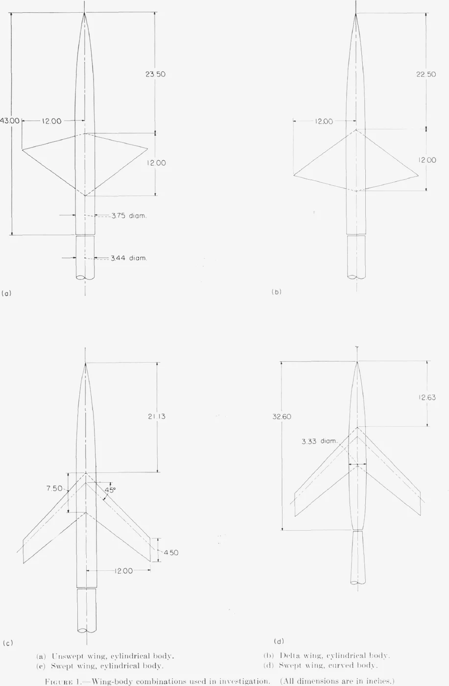
Basic bodies. Most results use three wings on one body of revolution, cylindrical over the wing region, 3.75 in. in diameter and 43.00 in. long, with the same forebody as the RM L52D01 model. The swept wing was also tested on that earlier model's curved body, 32.60 in. long with a slightly smaller maximum diameter of 3.33 in. (pp. 1–2, Fig. 1, Table I).
Wings. All three wings have an area of 1 sq ft, the reference area for every drag coefficient (p. 4), and a span of 24 in. (Fig. 1).
| Wing | Plan form | Aspect ratio | Taper ratio | Streamwise section |
|---|---|---|---|---|
| Unswept | 0° sweep of the quarter-chord line; root chord 12.00 in. | 4.0 | 0 | symmetrical circular arcs, 4% thick, maximum thickness at 40% chord |
| Delta | the unswept wing reversed: 75%-chord line unswept, leading edge swept 37° | 4.0 | 0 | as above, reversed |
| Swept | 45° sweep of the quarter-chord line; chords 7.50 and 4.50 in. | 4.0 | 0.6 | NACA 65A006 |
Special bodies. For each combination a comparable body of revolution was made by altering the original body so that its cross-sectional area at every station equals the total area of wing plus body there (Table II). A second family of indented bodies was cut down over the wing region so that wing plus indented body has the area distribution of the original body alone (Table III). With the radius at station and the wing's cross-sectional area cut by the plane at :
All areas are measured in planes normal to the airstream. The basic cylindrical body has in. from station 22.5 to 43.0.
| Station | Basic body | Comparable body | Indented body |
|---|---|---|---|
| 24.0 | 1.875 | 1.875* | 1.875 |
| 25.0 | 1.875 | 1.939 | 1.807 |
| 26.0 | 1.875 | 2.087 | 1.622 |
| 27.0 | 1.875 | 2.182 | 1.476 |
| 27.5 | 1.875 | 2.185 | 1.470 |
| 28.0 | 1.875 | 2.174 | 1.487 |
| 29.0 | 1.875 | 2.113 | 1.580 |
| 30.0 | 1.875 | 2.054 | 1.664 |
| 31.0 | 1.875 | 1.992 | 1.743 |
| 32.0 | 1.875 | 1.934 | 1.812 |
| 33.0 | 1.875 | 1.894 | 1.856 |
| 34.0 | 1.875 | 1.875 | 1.875 |
Table II gives 1.875 at station 23.5 and 1.892 at 24.5. The delta wing's tables are the same ordinates mirrored about station 29.0, since that wing is the unswept wing turned around
Measurementspp. 3–4
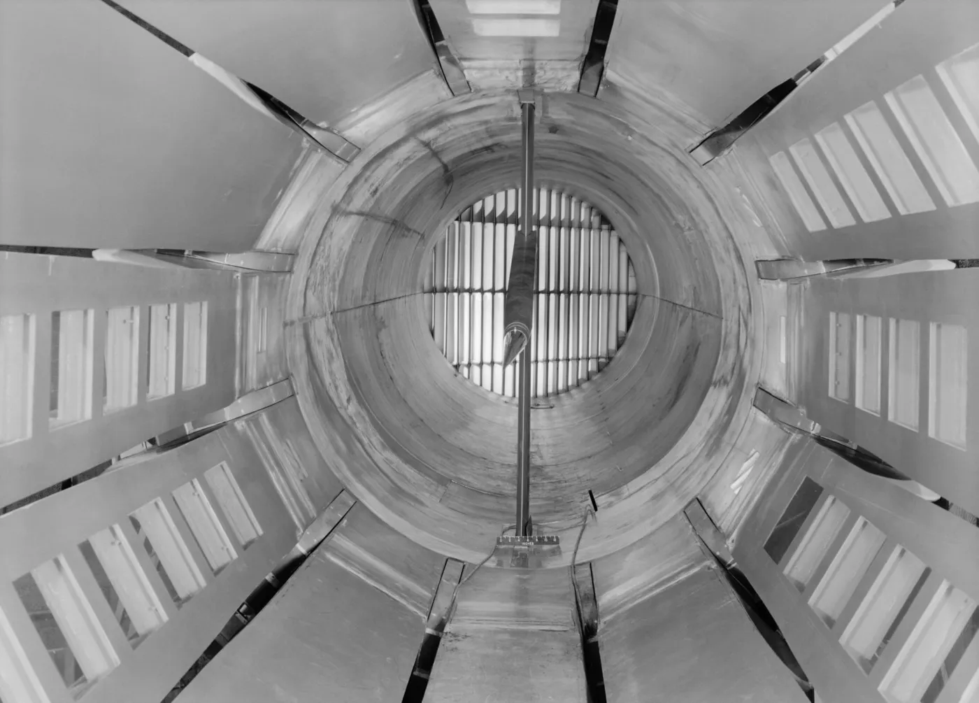
A temporary schlieren system photographed the flow. To see the field at a distance from the model with a centrally placed schlieren system, each model was displaced downward from the tunnel centre line, and each comparable body was displaced by exactly the same amount as its wing-body combination. Plan views of the unswept-wing combination were taken by rolling the model 90° and displacing it further (p. 3).
Wall Mach numbers came from rows of orifices along the centre lines of the test-section panels next to the top and bottom panels. For side views those stations lay 35.5 and 52.8 in. from the model centre line; for plan views, 31.2 and 58.0 in. Drag was measured with internal strain-gage balances, and base pressures were recorded (pp. 3–4).
Presentation of Resultsp. 4
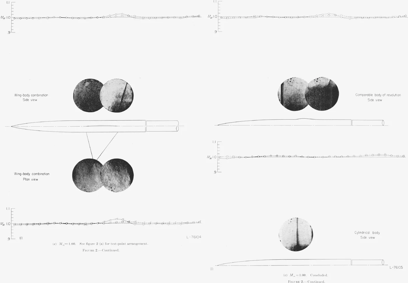
Detailed flow surveys. Figure 2 sets out, for several stream Mach numbers , composite schlieren photographs and wall Mach number distributions for three shapes: the unswept-wing combination, its comparable body, and the cylindrical body alone. Side views appear above the outline of each shape; plan views (for the wing-body combination only) appear below. The wall Mach distributions are placed so that their distance from the model outline is to scale, and their horizontal scale matches the model's (p. 4).
Stream Mach numbers varied by up to ±0.005 within a composite, but the directly compared side views of the combination and its comparable body differed by only about 0.003 (p. 4).
Drag coefficients. All drag coefficients are based on the 1-sq-ft wing area, even for the bodies alone, and are corrected to base pressure equal to free-stream static pressure. The drag rise is measured from the subsonic level, which removes most of the difference in skin friction between configurations:
is the zero-lift drag, the free-stream dynamic pressure, and sq ft.
The maximum error in absolute drag coefficient is about ±0.0005. Wall-reflected disturbances were essentially eliminated (by displacing the model, using a cylindrical afterbody on the larger body, and correcting for base pressure) except near Mach 1.05, where no data were taken (p. 4).
Results and Discussionpp. 4–20
The basic comparisons and analysis are made for the unswept wing on the cylindrical body. The other combinations show how changes to the wing and body affect the picture (p. 4).
Unswept Wing and Cylindrical Bodypp. 4–16
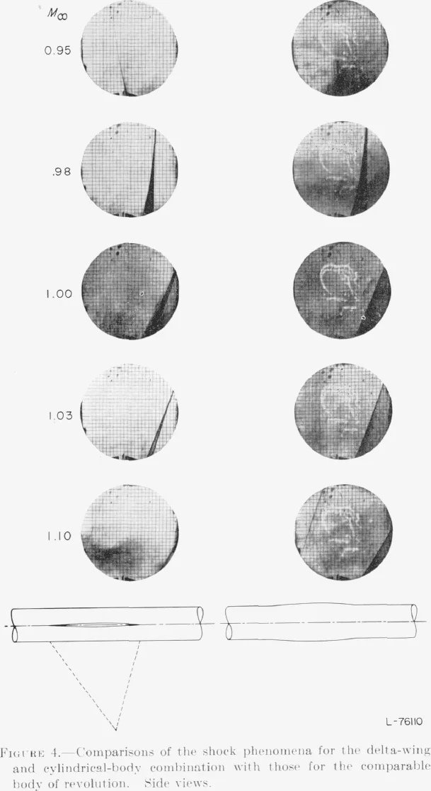
Shock phenomena. Near Mach 1, the extensive shock pattern of the unswept-wing combination is almost exactly the same as that of its comparable body, except in the region just downstream of the wing, where the two are still roughly comparable. (A stray shock crossing the plan view at Mach 1.03 is a weak reflection from the tunnel wall.) At Mach 1.10 the photographs are less alike (p. 4).
Why the shapes should match. The report traces the likeness to two related factors: near Mach 1, stream-tube areas hardly change with velocity (Busemann, TN 2687), and the effects of a disturbance are concentrated in a plane nearly normal to the stream. The second means the wing's disturbances appear at the same stations as the comparable body's, and it lets the flow in each cross-plane be considered on its own (p. 4).
- Take a circle in one cross-plane, centred on the axis and just outside the wing tip. Because the stream tubes are nearly invariant, the total radial deflection of the flow at that circle equals the surface displacement of the configuration in the same plane, and the two configurations have the same total (p. 15).
- The wing-body combination may still deflect the flow unevenly around the circle. Because the flow is essentially irrotational, those circumferential variations shrink with distance, and quickly, since the stiff, nearly invariant outer field pushes back with circumferential pressure gradients (p. 15).
- Those reactions converge toward the axis and even force the field near the wing into approximate likeness with the axisymmetric field of the comparable body (p. 16).
- Above Mach 1 the disturbance fields become conical and stream-tube areas do change with velocity, so the likeness should fade as speed increases (p. 16).
Drag characteristics. With the shock patterns so alike over most of the field, the shock losses should be nearly equal. Differences just behind the wing should matter little, because near Mach 1 the field is very extensive and most of the shock loss comes from the large region of strong shock outside it. With a thin, low-aspect-ratio wing and a gradually curved comparable body, shock-induced separation losses should be small and similar. So the drag rise of the combination should be about the same as that of the comparable body (p. 16).
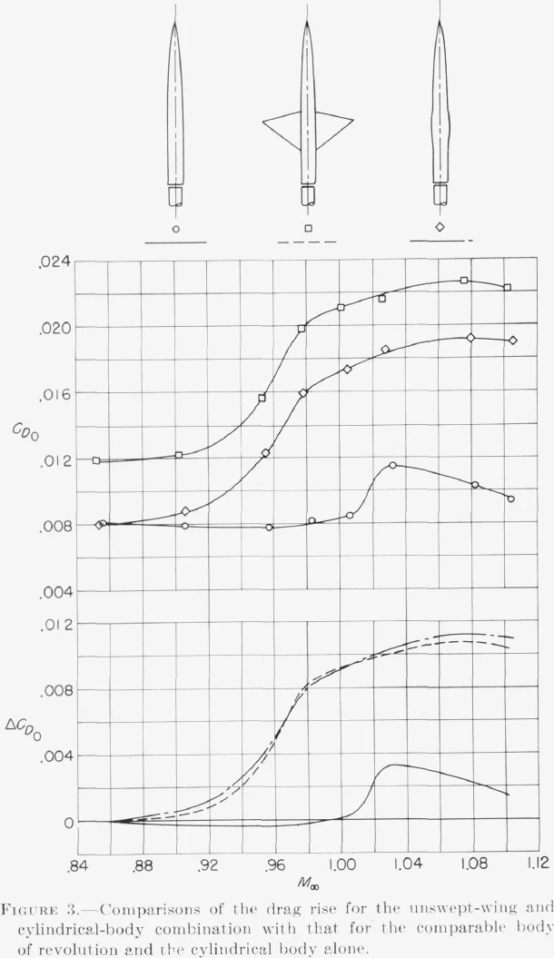
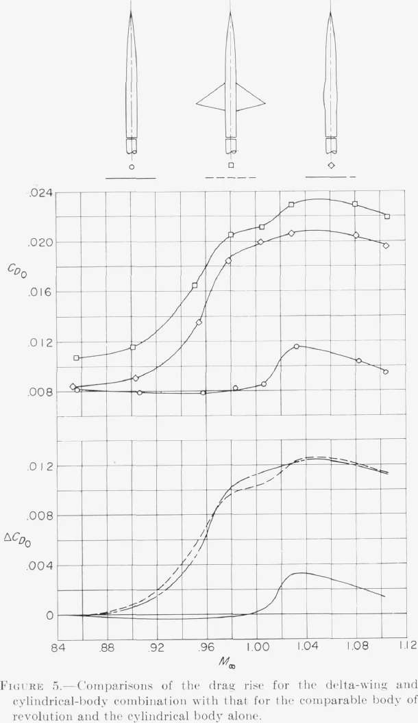
Measured increments for the combination and its comparable body agree within the accuracy of the data, though absolute levels differ, mainly through skin friction. The agreement suggests that secondary separation losses, as well as the primary shock losses, are essentially the same for the two, because the shock–boundary-layer relations are approximately the same. The visible differences in shock pattern at Mach 1.10 make no significant difference in shock loss (p. 16).
Delta Wing and Cylindrical Bodyp. 16
At a distance from the model the flow fields are almost exactly those of the comparable body at every test Mach number. Above the aft part of the wing the shocks match approximately, and, as for the unswept wing, the largest deviations probably lie behind the wing. The measured drag curve matches the comparable body's within the probable accuracy of the measurements (p. 16).
Swept Wing and Cylindrical Bodypp. 16–17
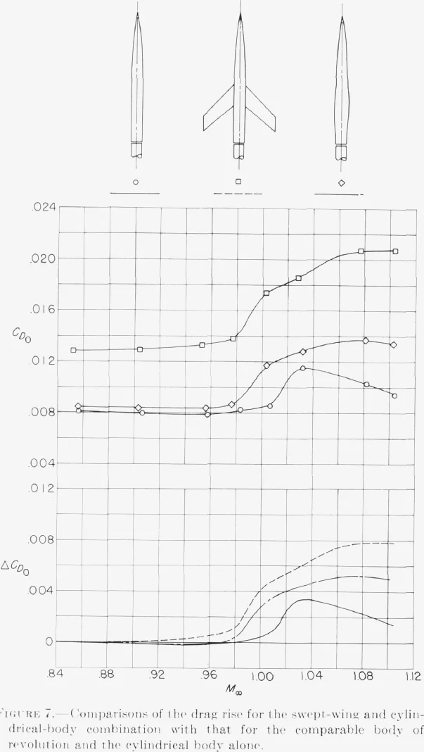
Far from the model the flow again matches the comparable body almost exactly. Near Mach 1 the swept wing produces a weak shock at the trailing edge of the wing-body juncture and a strong shock behind it, with another weak shock between them at Mach 1.03; the two weak shocks contribute insignificant loss. The wing's main shock is about the same as the comparable body's above the model but generally somewhat further aft; near the tip, especially at Mach 1.10, it differs (pp. 16–17).
The combination's drag increments are about 0.001 above those of the comparable body up to Mach 1.02, about the size of the combined possible measurement error. If real, the report attributes the difference to shock pattern and the associated boundary-layer separation, and the larger gap than for the unswept wing to the swept wing's greater thickness ratio and smaller taper. At higher Mach numbers the gap grows as the shock patterns diverge (p. 17).
Swept Wing and Curved Bodypp. 17–18
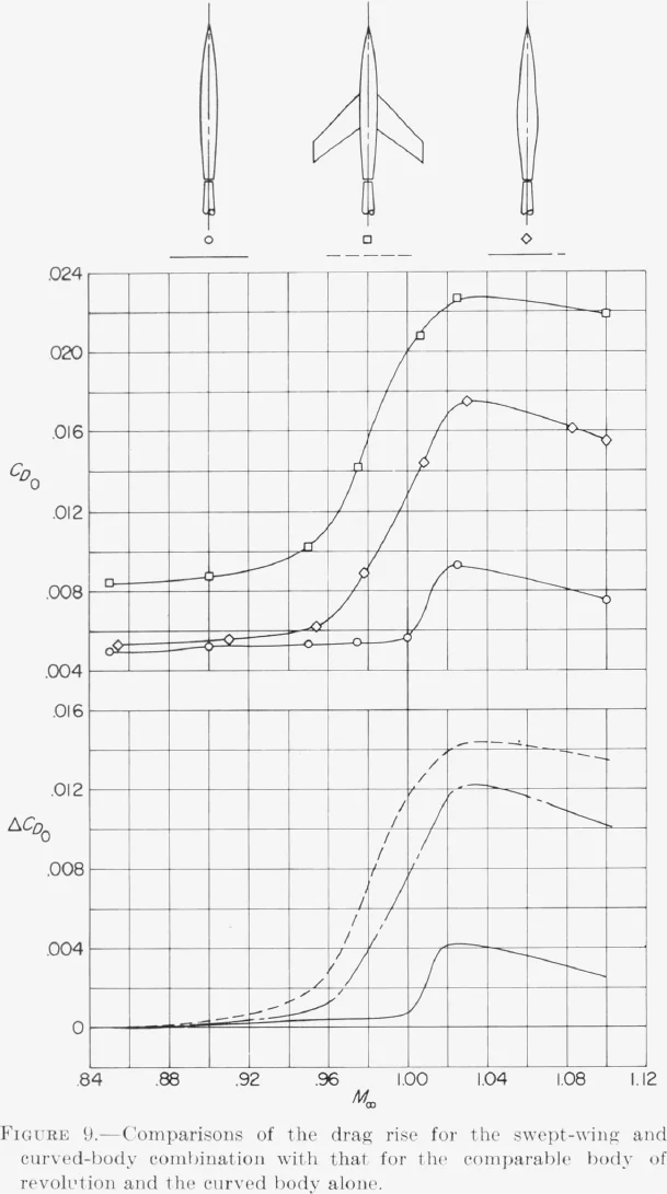
On the curved body, the swept wing's shocks are similar to, but apparently stronger than, those on the cylindrical body, and they differ from the comparable body's in the same way. The drag interference is severe: the drag-coefficient rise near Mach 1 is about 0.012, against 0.004 for the same wing on the essentially interference-free cylindrical body, partly perhaps because of the different maximum diameter and the strongly curved afterbody (pp. 17–18).
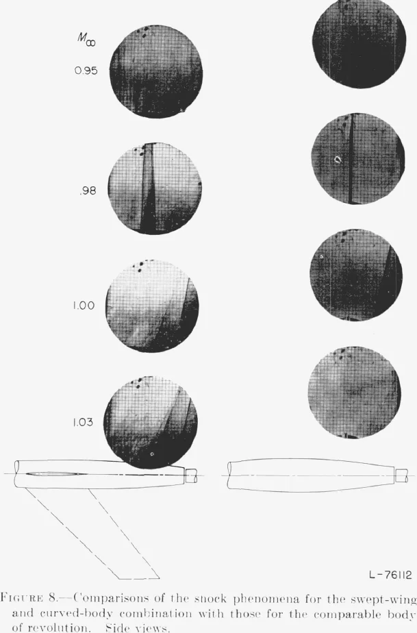
The combination's increments are about 0.003 above the comparable body's near Mach 1, and its maximum rise, at Mach 1.03, is about 15 percent greater. The key observation: the relative increase in drag rise from cylindrical to curved body is about the same for the wing-body combinations as for their comparable bodies (p. 18).
Generalizationpp. 18–19
To first order, then, the shock formations and drag rise of all four combinations are those of bodies of revolution with the same axial area developments, and those bodies are nothing more than area developments. Hence the concept: near Mach 1, the zero-lift drag rise of a low-aspect-ratio thin-wing–body combination depends primarily on the axial development of cross-sectional area, and any two such configurations with the same development have about the same drag rise (p. 18).
The author assumes, without direct test data, that it also holds for wings alone, for moderate twist or camber, and for yawed configurations. Linear theory (Graham, Douglas report SM-13346-A) and rocket-model experiments (RM L52D07) indicate a similar relation for slender non-circular bodies at supersonic and transonic speeds, and a similar relation for wave drag is implicit in Hayes's linearized supersonic theory (pp. 18–19).
Applications of Transonic Drag-Rise Conceptpp. 19–20
Correlation of drag-rise characteristicsp. 19
Quantitative correlation using the concept should become less accurate as thickness ratio, aspect ratio or taper ratio grows, and more so as Mach number rises above 1; ordinary changes of body shape should matter little. The wings of contemporary transonic and supersonic aircraft generally lie between the unswept and swept wings tested here, so their accuracy should too (p. 19).
Because the effect of detailed changes in area development was not known, quantitative correlation was not yet generally feasible. Qualitatively, though, all the available reliable drag-rise results for wings and wing-body combinations could be correlated using what was known about body shape and transonic drag rise, and so could nacelle–wing interference. A similar idea had been proposed in 1940 for estimating the critical speeds of wing-body combinations (p. 19).
Interpretation of variations of drag-rise characteristicspp. 19–20
Wing changes that slow the rate at which cross-sectional area develops, or lower the maximum area relative to the body, reduce the drag rise near Mach 1 (p. 19):
- The swept wing develops area more slowly and to a lower peak than the unswept wing (Table II), and its drag rise is smaller (Figs. 3 and 7).
- Reversing the unswept wing into the delta slows the area growth over the front of the wing but speeds the contraction over the rear, and the drag rise increases (Figs. 3 and 5). So, near Mach 1, a given rate of decrease in cross-sectional area generally results in a greater drag rise than does a similar increase.
- Adverse wing-body interference, as on the swept wing with the curved body, follows from the combination's area developing faster than either component's. Faster variations bring higher induced velocities and much stronger shocks, which act directly on the pressures on body and wing (p. 20).
Reductions of the drag-rise increments of wing-body combinationsp. 20
If drag rise follows area development, then indenting the body so that wing plus body matches the original body's area distribution should largely remove the wing's drag rise. The cylindrical body was indented this way for all three wings (Table III). Near the speed of sound the indentations cut the drag-rise increments of the unswept and delta wings by about 60 percent, and removed the swept wing's increment up to Mach 1.04; at higher Mach numbers their effect gradually declined (p. 20).
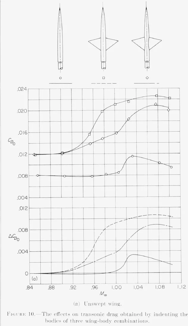
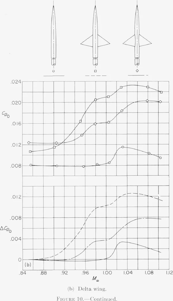
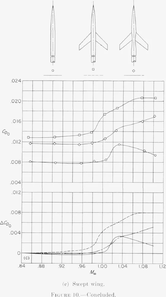
The indentations were designed without allowing for local induced flows or for the boundary layer's displacement of the stream tubes, which the report suggests may explain the incomplete effect on the unswept and delta wings; these matter less for the swept wing's more gradual indentation, and minor reshaping should do better. Above Mach 1 the benefit fades as the flow field changes character. At lift coefficients up to about 0.3 the indentations gave similar reductions (p. 20).
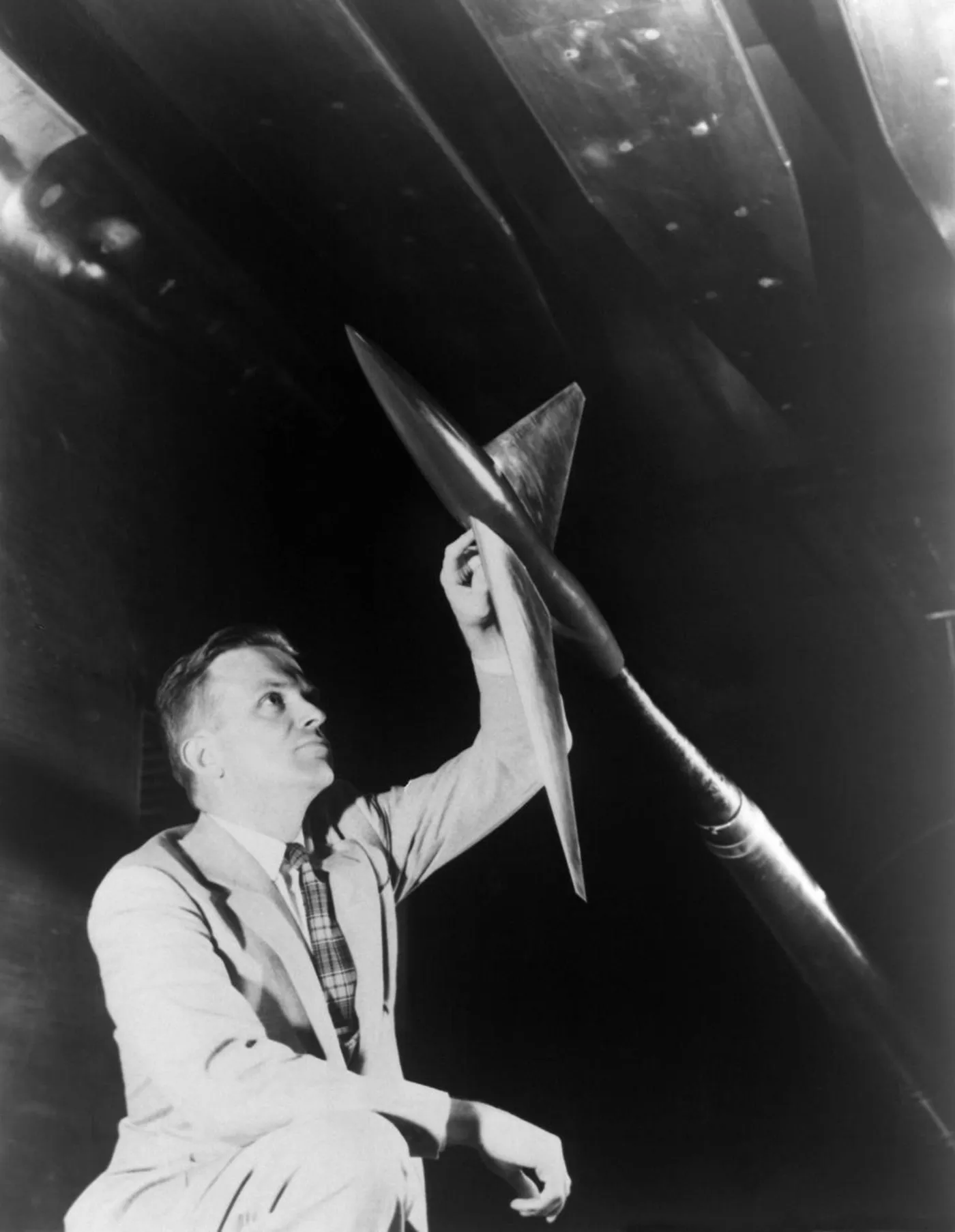
shaping the fuselage so that the development of cross-sectional area for the airplane approaches that for a low-drag body of revolutionOn obtaining the minimum transonic drag rise for an airplane, p. 20
Conclusionspp. 20–21
- The shock phenomena and drag-rise increments measured at zero lift near the speed of sound for these representative wing–central-body combinations are essentially the same as those for the comparable bodies of revolution.
- Near the speed of sound, the zero-lift drag rise of a low-aspect-ratio thin-wing–body combination depends primarily on the axial development of cross-sectional area normal to the airstream. The drag rise of any such configuration is therefore about the same as that of any other with the same area development.
Further, indenting the bodies of three representative combinations, so that each combination's area development matched the original body alone, greatly reduced or eliminated the wing's zero-lift drag-rise increment near the speed of sound (p. 21).
Assumptions and open questions
Key assumptions
- Near Mach 1, stream-tube areas are taken as essentially invariant with velocity, so a disturbance's effect is concentrated in a plane nearly normal to the stream and each cross-plane can be considered on its own (p. 4).
- The flow is treated as essentially irrotational outside the configuration, which is what lets circumferential differences between a wing-body and its comparable body die out with distance (p. 15).
- Drag rise is dominated by shock losses, with shock-induced separation small and similar for the compared shapes, because the wings are thin and of low aspect ratio and the comparable bodies gently curved (p. 16).
- Subtracting each configuration's drag at about Mach 0.85 is taken to remove the differences in skin friction, so that the increments can be compared directly (p. 4).
- The indented bodies were designed from geometric area alone, without allowance for local induced flows or boundary-layer displacement of the stream tubes (p. 20).
Where further work would help
- Mach range. The comparisons run from Mach 0.85 to 1.10, with no data near 1.05, and the likeness already weakens by 1.10 (p. 4). How far above Mach 1 the area rule stays useful as a design guide is left open.
- Wing geometry. Three wings were tested, with thickness ratios of 4 and 6 percent and aspect ratio 4. The report expects accuracy to fall as thickness, aspect ratio or taper ratio grows (p. 19); systematic tests across those parameters would map that sensitivity.
- Twist, camber, yaw and lift. The concept is assumed, without direct tests, to hold for wings alone, for moderate twist or camber, and for yawed configurations (p. 18). Indentation was checked only up to lift coefficients of about 0.3 (p. 20).
- Detailed area shape. Quantitative correlation awaited knowledge of how detailed changes in the area distribution affect drag rise (p. 19). The delta-wing result, where contraction cost more than expansion, points to a shape effect beyond peak area alone.
- Refined indentations. Allowing for induced flow and boundary-layer displacement is expected to cut the unswept and delta increments further (p. 20). The subsonic drag of each indented combination, which sets the base from which its rise is measured, is a further quantity to examine alongside the rise.
- Full airplanes. The models are 33 to 43 in. long wing-body combinations without tails or nacelles. Nacelle–wing interference was correlated only qualitatively, and the report calls for specific experimental comparisons to define how the concept applies there (p. 19).
- Lowest-drag shape. The closing suggestion, shaping the fuselage so the airplane's area development approaches that of a low-drag body of revolution of the highest feasible fineness ratio (p. 20), is a direction for design rather than a tested result in this report.
What happened next
- 1951
Late in the year, after wing-fuselage tests in the slotted-throat 8-foot tunnel and a symposium talk by Adolf Busemann on transonic flow, Whitcomb conceives the area rule (NASA SP-4219, ch. 5; NASA Langley).
- 1952
Area-rule models are tested early in the year, and the findings are classified. The research memorandum, RM L52H08, goes to cleared manufacturers in September; Convair engineers had already been shown the results at Langley in mid-August (SP-4219, pp. 143–146).
- 1954
On 16 August Grumman's area-ruled F9F-9 (later the F11F Tiger) exceeds the speed of sound in level flight without afterburner. On 24 December the reshaped Convair F-102A flies, going supersonic in level flight and in its initial climb; NASA estimates the changes raised its speed by about 25 percent (SP-4219, pp. 145–146).
- 1955
The area-rule work is declassified in September. Whitcomb receives the 1954 Collier Trophy for the discovery and experimental verification of the area rule (SP-4219, pp. 135, 147).
- 1956
The study is republished as NACA Report 1273. NASA Langley later writes that the area-rule concept has been incorporated in virtually every high-performance military aircraft since.
Sources
- NACA Report 1273 on NTRS · Public use permitted
- NACA RM L52H08 (1952) on NTRS · The original research memorandum
- Lane E. Wallace, "The Whitcomb Area Rule: NACA Aerodynamics Research and Innovation", NASA SP-4219, ch. 5
- NASA Langley: Richard T. Whitcomb
- NASA: Richard Whitcomb examines model (1955)
- NASA Image Library: 8-Foot High Speed Tunnel, LRC-1957-B701_P-00959