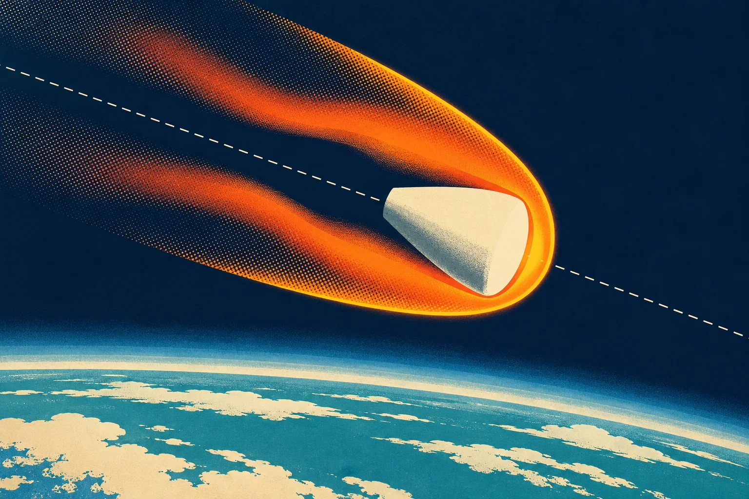
At a glance
- Category
- An analytical study. A simplified, generalized motion analysis (constant drag coefficient, exponential atmosphere, gravity neglected) is combined with Reynolds' analogy and a stagnation-point heat-transfer relation to compare the convective heating of different missile shapes. In the authors' words, the aim is to show in the broad sense the means available for minimizing the heating problems (p. 1).
- Context
- Written at Ames in 1953 (p. 13) for long-range ballistic missiles, with entry speeds of 10,000 to 30,000 ft/s as its examples. It builds on Wagner's laudably simple motion analysis for a particular missile (ref. 1, p. 1), the NACA standard atmosphere (refs. 2–3), Sibulkin's stagnation-point heat-transfer result (ref. 5), and cone pressure-drag and turbulent boundary-layer data (refs. 6–9).
- Contributions
- A closed-form velocity and deceleration history for a body entering on a straight path, eqs. (13)–(21), with universal curves and (Fig. 4).
- The result that peak deceleration, , depends only on entry speed and angle, not on mass, size or drag coefficient, provided it occurs above sea level (eq. 17).
- A total-heat formula, eq. (33), showing that the heat reaching the body is the entry kinetic energy times half the ratio of friction drag to total drag, times a factor set by the parameter (eq. 51).
- The design rule that follows: relatively light bodies should be blunt, with high pressure drag; relatively heavy bodies should be slender, with low skin friction (pp. 8–9).
- Formulas for peak average and stagnation-point heating rates, eqs. (37) and (46), with the altitudes and speeds at which they occur, and the case for a large nose radius (p. 11).
Summaryp. 1
The report makes a simplified analysis of the speed and deceleration of ballistic missiles entering the atmosphere at high supersonic speed, then uses it to find how a designer can minimise aerodynamic heating. Gravity turns out to be small next to drag, so the path is essentially a straight line. With a constant drag coefficient and density falling exponentially with altitude, the speed and deceleration follow generalised curves (p. 1).
A curious finding is that the maximum deceleration is independent of physical characteristics of a missileSummary, p. 1
On heating, the conclusion depends on how heavy the missile is. A missile heavy enough to be slowed only slightly is heated least when its total shear force is least, which favours shapes with low pressure drag. A missile light enough to be slowed to low speed is heated least with shapes with a high pressure drag, because that delivers most of the heat to the atmosphere. Blunt shapes also have lower peak heating rates at the nose. The summary closes by saying the blunt, high-drag shape would appear to offer considerable promise for missiles of the usual sizes, weights and speeds (p. 1).
Introductionp. 1
Re-entry is called one of the most difficult phases of a long-range ballistic flight. Boundary-layer air may reach tens of thousands of degrees Fahrenheit, so heat-absorbing material is needed to keep the missile intact. Every pound carried to burnout costs many pounds of booster fuel, so that protective material must be kept to a minimum (p. 1).
The total heat matters, but so does the rate. A shell that absorbs heat can conduct it inward only so fast. Too high a rate creates temperature differences that can spall the surface or cause structural failure from thermal stress. For liquid cooling, the rate sets the pumping or transpiration requirement. Earlier missile studies had been very detailed in scope. This report aims instead at a generalised analysis that makes the salient features of the problem clear (p. 1).
Analysispp. 2–7
Motion of the Bodypp. 2–5
A body of mass enters the atmosphere from great height. At altitude its speed is and its flight path makes an angle with the horizontal; is horizontal distance from the impact point. With drag coefficient , reference area , air density and gravity , the equations of motion are (p. 2):
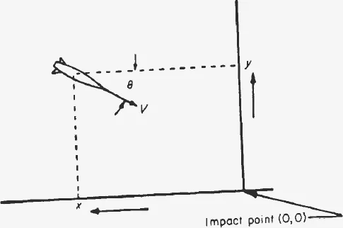
Units: in ft/s, in sq ft, in slugs, in slugs/ft³. A footnote notes that Earth's rotation and curvature are ignored because the altitudes where drag matters are under 1 percent of Earth's radius.
varies with Mach and Reynolds number, and and vary with altitude, so an exact solution is formidable. The report first takes a simplified case: vertical descent, constant drag coefficient (accurate at high Mach number when pressure drag dominates), constant gravity (it falls only 1 percent per 100,000 ft), and an isothermal, exponential atmosphere (p. 2):
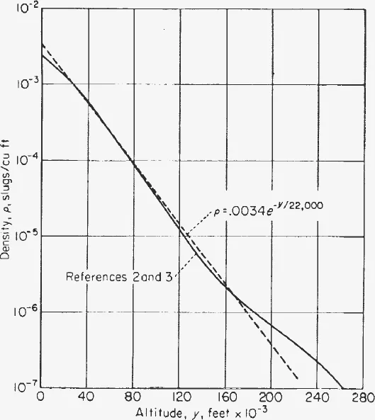
Substituting turns eq. (3) into a linear equation, eq. (4), solved exactly as a series in eqs. (5)–(6). The constants are fitted where the deceleration is large: slugs/ft³ and ft⁻¹, giving
In good agreement with the NACA standard atmosphere from 20,000 to 180,000 ft (refs. 2 and 3, p. 2).
The worked example is a solid iron sphere 1 ft in diameter, with on frontal area (valid above about Mach 1.4), falling vertically from 40 miles at 10,000, 20,000 and 30,000 ft/s. The full equation gives the solid curves of Figs. 2 and 3. Decelerations reach large multiples of , which suggests dropping gravity (p. 3):
is the entrance speed. At 40 miles the exponential factor is very nearly unity, so the speed there is essentially .
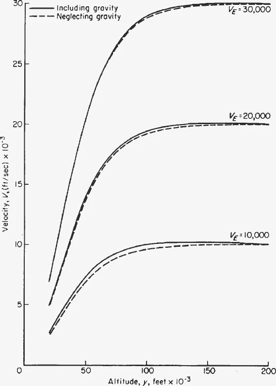
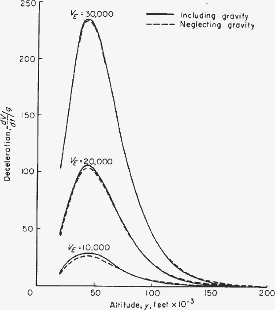
The close agreement means that for any entry at high speed and a not-too-shallow angle , gravity can be dropped from eq. (1). The path is then a straight line at , and with the equation integrates in closed form (p. 4):
Setting the derivative of eq. (14) to zero gives the altitude of peak deceleration, the speed there, and the peak itself:
Eqs. (16)–(17) apply only if . Otherwise the peak comes just before impact, at the speed of eq. (20), with the value of eq. (21).
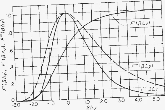
Measured from , with the height above it, speed and deceleration collapse onto two universal functions (p. 4):
Heating of the Bodypp. 5–7
The heat that enters a missile must be absorbed by some coolant material, often the shell itself, which can take only a fixed amount of heat per unit weight. So the total heat input must be minimised. Thermal stress in the shell depends on the time rate of heat input, both the average over the surface (for the structure as a whole) and the local rate where it is greatest. The report compares missiles with one another rather than computing absolute heating, under five assumptions (p. 5; discussed in Appendix B):
- Convective heat transfer predominates; radiation is negligible.
- Effects of gaseous imperfections may be neglected.
- Shock-wave boundary-layer interaction may be neglected.
- Reynolds' analogy is applicable.
- The Prandtl number is unity.
Total heat inputpp. 5–6
The convective heating rate per unit area (ft-lb/ft²) at a surface element is set by the local heat-transfer coefficient , the recovery temperature and the wall temperature . At high Mach number the recovery temperature far exceeds any allowable wall temperature, so the driving temperature difference becomes simply the kinetic energy per unit heat capacity ( is the specific heat at constant pressure, the ratio of specific heats, and the local Mach number and static temperature) (p. 5):
Reynolds' analogy ties heat transfer to skin friction: , eq. (26), where is the local skin-friction coefficient. Integrating over the whole surface gives the heat transferred per foot of descent, in terms of an equivalent friction coefficient , assumed constant with altitude (p. 6):
A footnote explains the constant- assumption: Mach- and Reynolds-number effects nearly compensate, and for typical conical missiles varied by at most about 50 percent over the altitudes where 80 percent of the heat is transferred.
With eqs. (2) and (13), eq. (27) has exactly the shape of the deceleration, eq. (14). The altitude rate of heating is therefore proportional to the deceleration, peaks at the same altitude , and follows the same curve (eqs. 29–32). Integrating from entry to impact gives the total heat (p. 6):
is the impact speed. The factor is the friction drag as a fraction of the total drag.
Maximum time rate of average heat input per unit areap. 6
Averaged over the surface, the heating rate is , eq. (35). Along the trajectory it peaks a little higher than the deceleration does, at a higher speed:
Relative to its peak it again follows , now measured from (eq. 40). If , the peak is at sea level: , eq. (41).
Maximum time rate of local heat input per unit areapp. 6–7
The hottest spot is normally the nose tip. A truly pointed nose would burn away: its local heating rate is very large and it has little capacity to hold heat. So practical noses are nearly hemispherical. Ahead of any truly blunt body the bow shock is detached, with a stagnation point at the nose. Behind the normal part of the shock the flow is subsonic and very hot, so the nose of radius can be treated as a sphere in subsonic flow (pp. 6–7).
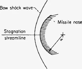
For laminar, incompressible flow near the stagnation point, the Nusselt number from ref. 5 is , with the gas conductivity and its viscosity at the recovery temperature. With , eq. (25), and viscosity varying as at high temperature (p. 7):
A footnote adds that compressibility and dissociation tend to raise the constant by as much as a factor of 2 in the speed range of the report, which does not affect the comparative purpose.
Along the trajectory, the stagnation-point rate peaks highest and earliest of the three quantities:
Relative to its peak it follows , eq. (49). If , the sea-level value is , eq. (50).
Discussionpp. 7–12
Motionpp. 7–8
Drag deceleration is generally large compared with gravity, so the missile keeps the flight-path angle it had at entry. For most missiles the peak deceleration occurs aloft, and then (p. 7):
- the peak deceleration depends only on entry speed and flight-path angle, eq. (17), and not on mass, size or drag coefficient;
- the speed at that moment is a fixed 61 percent of the entry speed, eq. (16);
- the altitude of the peak depends on the body and the flight-path angle, but not on the entry speed, eq. (15);
- above and below that altitude, speed and deceleration follow the fixed curves of Fig. 4.
A very heavy missile may have a fictitious (negative) . Its largest deceleration then comes just before impact, is smaller than eq. (17), and does depend on the body, eq. (21). Fig. 4 still gives the variation with altitude, measured from the fictitious (p. 8).
Heatingpp. 8–12
Total heat input. The best course for the designer depends on one dimensionless group, the ratio of drag area to mass scaled by the atmosphere and the entry angle (p. 8):
For a relatively heavy missile, : the missile is retarded only slightly and expanding eq. (33) gives a heat input proportional to the total shear force . Least heat then means least skin friction. For a relatively light missile, : nearly all the entry kinetic energy is lost before impact and the heat input approaches a fixed fraction of it (p. 8):
The light-body result is the heart of the report. It is, the authors note, at first glance a rather surprising result: heating goes down as total drag goes up, as long as friction drag does not rise as fast. The entry kinetic energy must end up as heat in the air and the body together. The body's share is . Making that ratio small, by making most of the drag pressure drag, gives as much of the energy as possible to the atmosphere. A footnote adds that even if all the drag were friction, only half the heat would reach the body; the other half is left in the boundary layer and wake (p. 8).
To illustrate, the report computes the heat at impact for two families of cones entering at : a fixed base area of 10 sq ft, and a fixed volume of about 16 cu ft (16.34 cu ft in the figure captions). Gross weights are 0, 1,000, 5,000, 10,000 lb and infinite, at 10,000, 20,000 and 30,000 ft/s. Pressure drag comes from refs. 6 and 7 (base drag neglected) at the entry Mach number with R. The boundary layer is taken as wholly turbulent, since the Reynolds number always exceeded about and reached the order of billions for slender cones (p. 8).
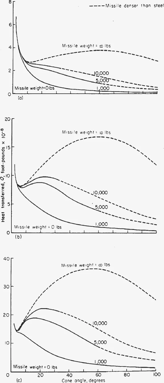
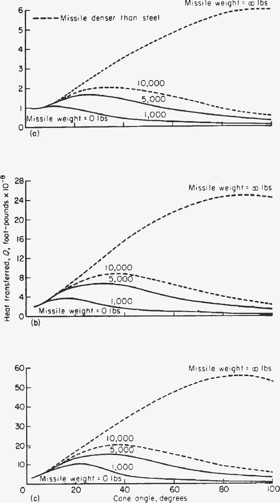
Curves for missiles denser than steel are dashed because they are improbable. For both families, the heavy missile does best with a small cone angle (small ), increasingly so at higher speed, and the light missile does best with a large cone angle (small ) (pp. 9–10).
Average heating rate. Treating the shell as a slab that conducts heat inward, the average thermal stress in the shell is greatest when is greatest. Again the answer depends on (p. 10):
Heavy missiles should minimise ; light ones should minimise . In the cone calculations was evaluated at , or at sea level when .
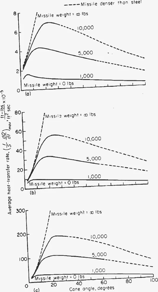
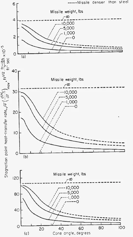
Local heating rate. The stress at the nose, where local heating is probably greatest, is many times larger than the average and may call for extra cooling such as transpiration even with copper or silver shells. Because the stagnation rate varies inversely with the square root of the nose radius, eq. (44), pointed noses should be avoided and the nose radius made as large as possible. For a fixed radius, mass, speed and angle, the only lever left is to raise . The report defines a relative factor , the peak stagnation rate divided by the peak the same missile would have if it were infinitely heavy (p. 11):
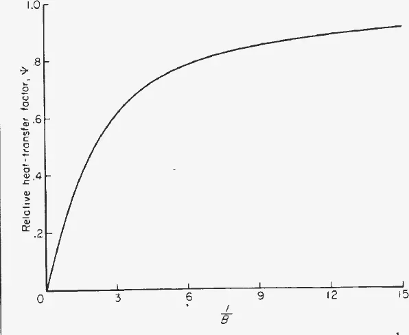
For the cone families, the pointed tips are replaced by spherical tips of radius (with unchanged), and is plotted against cone angle. It is seen again that the large-angle, high-drag cones are considerably superior (p. 12).
Design Considerations and Concluding Remarkspp. 12–13
The two aspects of the problem lead to complementary rules. For total heat, a relatively light missile needs the least coolant with a blunt, high-pressure-drag shape, and a relatively heavy one with a long, slender, low-friction shape. For heating rate, the peak average rate is lowered by either a blunt or a slender shape, while missiles of intermediate slenderness were definitely to be avoided. The nose stress is lowest with the largest permissible tip radius and overall drag coefficient, so the blunt, high drag shape always appears to have the advantage there (pp. 12–13).
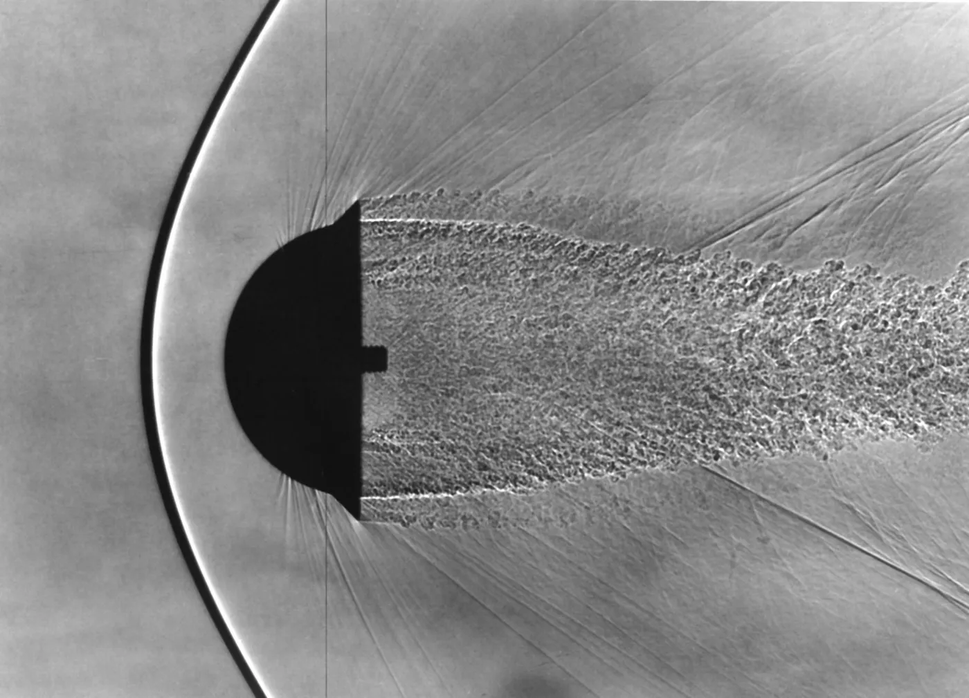
A heavy re-entry body, especially at 20,000 ft/s or more, might be a slender cone with the largest practicable nose radius, possibly with transpiration cooling at the tip. The light case, which the authors expect to be the more usual one, gets more attention. For it they single out the sphere (p. 13):
- It is a high-drag shape, with friction only a few percent of the total drag.
- It has the maximum volume for a given surface area.
- Its continuously curved surface is inherently stiff and strong.
- Its large stagnation-point radius reduces the peak thermal stress in the shell.
- Its aerodynamic forces do not depend on attitude, so it may need no stabilising surfaces.
- It could be rotated slowly, even randomly, to spread the heating evenly over the shell.
If it is rotated, slow, random motion may be needed so that Magnus forces do not pull it off course, and gun-fired spheres had shown large lateral motions at subsonic and low supersonic speeds (ref. 10). The sphere, like any very high-drag shape, may be unacceptable if its low terminal speed (wind drift) or its peak deceleration cannot be allowed. A flow-separating spike could roughly halve its drag (ref. 11). Both drawbacks could be eased by variable geometry: a round-nosed body with a low-angle conical afterbody and an extensible skirt at the base, flared during the intense-heating phase and then retracted to shape the deceleration and speed history (p. 13).
The authors close with two cautions. The treatment is relative, and there is, clearly, no substitute for step-by-step calculation in a final design. And the neglected effects (dissociation, shock-wave boundary-layer interaction, radiation) are not expected to change the blunt-versus-slender conclusions up to about 10,000 ft/s, but cannot be assumed negligible at higher speeds, where better data on hot air are needed (p. 13).
Appendix A · Symbolsp. 14
The full symbol list. The main ones used above: drag reference area (sq ft); the parameter of eq. (51); drag coefficient; equivalent friction coefficient, eq. (28); specific heat at constant pressure; heat per unit area (ft-lb/ft²); total heat (ft-lb); mass (slugs); surface area; , entry and impact speeds; altitude; , the atmosphere constants of eq. (2); entry angle; nose radius; relative stagnation heating factor. Subscripts 1, 2, 3 mark the peaks of deceleration, average rate and stagnation rate.
Appendix B · Simplifying Assumptions in the Calculation of Aerodynamic Heatingpp. 15–16
Each of the five heating assumptions is examined against entry speed (pp. 15–16):
| Assumption | Around 10,000 ft/s | 20,000 ft/s and above |
|---|---|---|
| 1. Radiation negligible | Gas-to-body radiation negligible compared with convection | May need to be considered for massive blunt bodies near 20,000 ft/s; may be comparable to convection near 30,000 ft/s |
| 2. Gaseous imperfections negligible | Air not hot enough for dissociation to matter | Disturbed air may exceed 10,000°R; appreciable dissociation expected |
| 3. No shock-wave boundary-layer interaction | Covered by the appendix's overall conclusion for these speeds | May significantly raise laminar skin friction above about Mach 10 (refs. 14, 15) |
| 4. Reynolds' analogy | In line with Rubesin's work (ref. 16) | Not established a priori |
| 5. Prandtl number of 1 | Permissible for relative heating | Effect of dissociation on Prandtl number unclear |
Surface radiation is neglected on the premise that allowable wall temperature, and so surface radiation, is about the same for every shape. The radiation estimates treat air as a grey body with Wien's law and neglect dissociation, which makes them conservative.
The appendix concludes that the simplifications will not significantly influence the results near or below 10,000 ft/s, but that at 20,000 ft/s and above the results must be viewed with skepticism until the static and dynamic properties of air at those conditions are better known (p. 16).
Assumptions and open questions
Key assumptions
- Gravity is neglected during the drag-dominated part of entry, so the path is a straight line at the entry angle ; the report notes this needs to be not too small (p. 4).
- The drag coefficient is constant along the trajectory, which the report ties to high Mach numbers where pressure drag dominates (footnote 3, p. 2).
- The atmosphere is isothermal and exponential, , fitted between 20,000 and 180,000 ft (p. 2); Earth's rotation and curvature are ignored (footnote 2, p. 2).
- Heating is convective only, with Reynolds' analogy, Prandtl number 1, no dissociation, no shock-wave boundary-layer interaction and no radiation (p. 5, Appendix B).
- The wall stays much cooler than the recovery temperature, so the driving temperature difference is (eqs. 24–25, footnote 6).
- The equivalent friction coefficient is constant with altitude (footnote 7, p. 6), and the stagnation-point relation assumes laminar, incompressible flow near the nose (p. 7).
- The comparisons are relative, aimed at ranking shapes, not at absolute heat loads (p. 5).
Where further work would help
- Higher entry speeds. The authors themselves limit firm conclusions to about 10,000 ft/s. Real-gas properties of air, radiation from the shock layer and dissociation at 20,000–30,000 ft/s would show how far the blunt-body ranking carries to faster entries (p. 13, Appendix B).
- Shallow entry angles. The straight-line solution rests on large deceleration compared with gravity. Entries at small , where gravity and Earth's curvature bend the path, would test how the peak-deceleration and heating formulas extend.
- Variation of drag and friction with altitude. and are held constant; footnote 7 cites up to about 50 percent variation in . Following them along the trajectory would show how sensitive the cone comparisons of Figs. 5–11 are to these choices.
- Laminar versus turbulent flow. The cone totals assume a wholly turbulent boundary layer, while the nose formula is laminar. How the conclusions shift with transition location is a natural sensitivity study.
- Absolute heat loads and wall temperature. Turning the relative results into coolant weights needs the wall-temperature history the report sets aside (footnote 6) and the factor-of-2 compressibility correction it mentions for eq. (44).
- Stability and dispersion. The sphere's case depends on attitude-insensitivity, slow rotation and acceptable lateral motion, which the report flags as unknown at high supersonic speed (p. 13).
What happened next
- 1951
Late in the year Allen conceives the blunt-body theory, according to NASA's history of Ames. Eggers joins him on the trajectory analysis.
- 1952
September: Allen personally submits his findings to select people in the missile industry. The secret research memorandum, dated April 28, 1953, goes out to industry and the military the next spring.
- 1954
By the beginning of the year the U.S. Air Force has changed the architecture of its ballistic missiles to embody the blunt-body concept. NASA's Mercury history records that the principle led directly to General Electric's Mark I and Mark II nose cones for the Atlas and later the Thor.
- 1957
Allen receives the NACA Distinguished Service Medal and gives the Wright Brothers Lecture on December 17. The work appears publicly as NACA TN 4047, later superseded by Report 1381 in NACA's 1958 annual report.
- 1959
Project Mercury adopts H. Julian Allen's blunt-body concept to bring a man back from 100 miles up at about five miles per second, and NASA's wind tunnels turn to blunt-capsule stability testing.
- 1965
Allen becomes the second Director of Ames Research Center, serving from October 15, 1965 to November 15, 1968.
Sources
- NACA Report 1381 on NTRS · Public use permitted
- E. P. Hartman, Adventures in Research: A History of Ames Research Center 1940–1965 (NASA SP-4302), pp. 215–218, 268, 278
- L. S. Swenson, J. M. Grimwood & C. C. Alexander, This New Ocean: A History of Project Mercury (NASA SP-4201), pp. 60–62, 142 and note 20
- W. G. Vincenti, J. W. Boyd & G. E. Bugos, H. Julian Allen: An Appreciation (Ames History Archives)
- NASA: H. Julian Allen
- NASA Image Library: Allen explaining the blunt-nose principle, 1957
- NASA Image Library: Allen at the 8-by-7-foot Supersonic Wind Tunnel, 1957
- NASA Image Library: Shadowgraph of a hemispherical model in free flight, 1958